 |
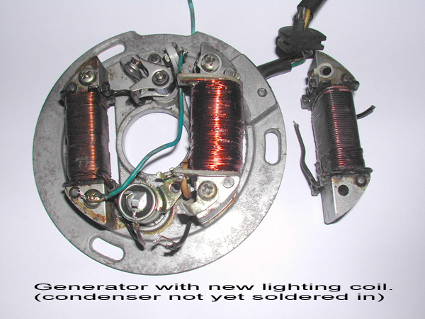
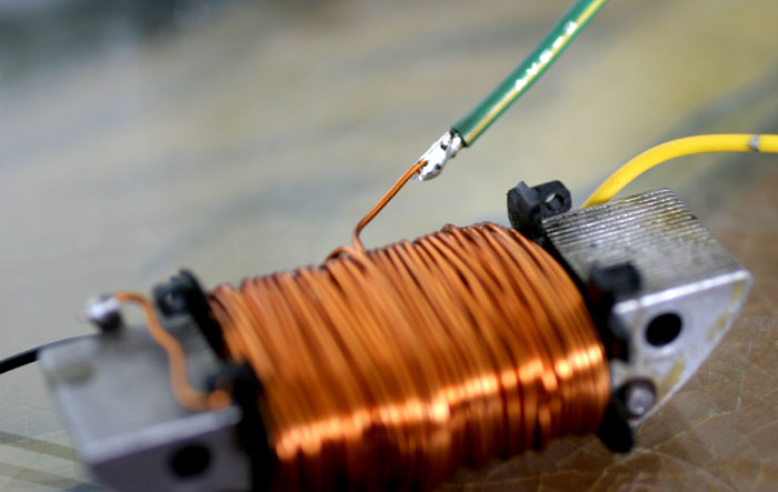
Here's the new coil fitted and
compared with the old burnt coil alongside for comparison.
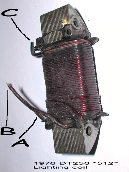
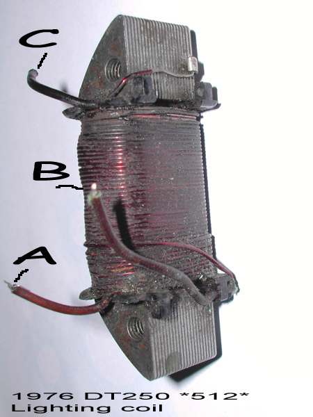
A = Green/Red |
| ( During the work I was giving the old girl a "tune up" and had not yet wired the new condenser and contact points.) | |
DT 250 (model 512) Lighting Coil
rebuild
(Part number 498-81313-21)
| Way back, the lights failed on my 1976 DT250. The fault was diagnosed as a burnt Lighting Coil, I ordered one from the local Yamaha dealers but was told they were on "extended back order". I paid £45 and waited... 3 months later a part arrived and was duly fitted. Visually it was different but I was assured it was "the revised part for your bike". After fitting it was obvious that it was not correct. Symptoms - dim lights and overcharging of the battery. |
| With a test meter across the
disconnected generator leads (plug) I got the following readings:-
green/red to ground, 9.5 volts @ 2,000
r.p.m. and 36 volts @ 6,000 r.p.m. Obviously very wrong.... To add insult to injury, the Yamaha dealers wouldn't take the part back because "it was 'used' and as a 'special order' there was no refund policy" |
| Having scoured E-Bay, other parts dealers and various "Auto Jumbles" all with no success, I decided to have a go at rewiring the coil myself. |
Old Coil
|
|
Here's the new coil fitted and
compared with the old burnt coil alongside for comparison.
A = Green/Red |
| ( During the work I was giving the old girl a "tune up" and had not yet wired the new condenser and contact points.) | |
Create a coil !!!
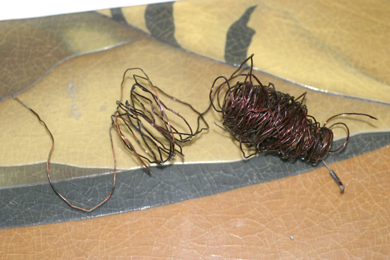 |
Un-wind the first turn of the wire and double check the wire gauge, making sure the new wire is very close to the existing wire in diameter... Ideally, measure it with a micrometer or vernier gauge. The lacquer will make absolute measurements impossible. Only go up to the next wire size if the existing wire is between "normal" wire sizes... (Mine measured 0.82mm, so I used 0.9mm - which is 20 SWG). When unwinding the wire it will be messy and bits of burnt lacquer will go everywhere and can be very sharp! Write down the number of turns where each take-off occurs. |
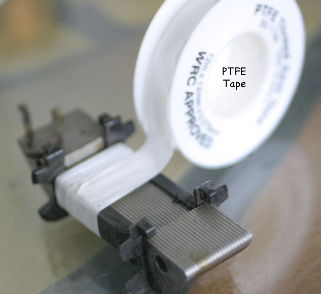 |
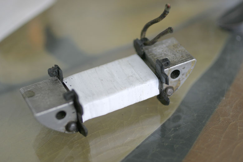
Clean up the laminated soft iron core and any 'former' pieces. (The formers on mine were burnt and very brittle, so handle gently!) To be double sure, I wound the centre with PTFE tape to ensure it all stayed together and to doubly insulate the centre windings as this was a hand wound exercise... |
 |
I went around the centre about
5-6 layers to make a nice 'base' for the copper windings. The tape is
only 7 thousandths of an inch thick, so it doesn't hurt to wrap plenty
on... The little tag of wire on the top right was just a reminder as to where the end of the wire needed to be when completing the last turn... |
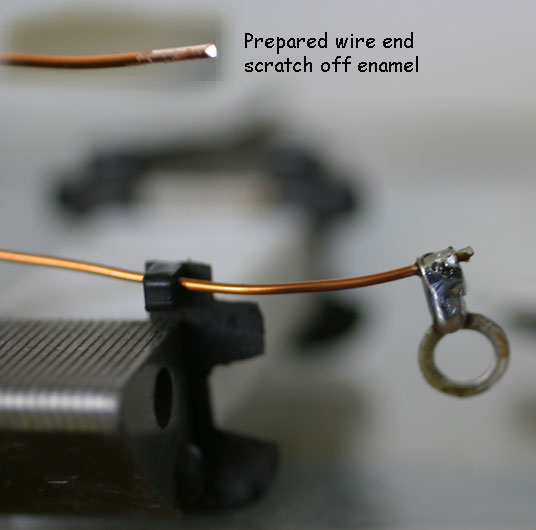 |
Scrape off the enamel/lacquer
to enable the wire to be 'tinned'. Make sure you leave enough wire
protruding so the earth tab can reach the mounting hole - difficult to
correct afterwards (smile).
When soldering, remember to 'tin' both parts before final soldering. Also, copper wire really does conduct heat fast along the wire, so be wary of burnt fingers if you hold the wire steady when soldering... |
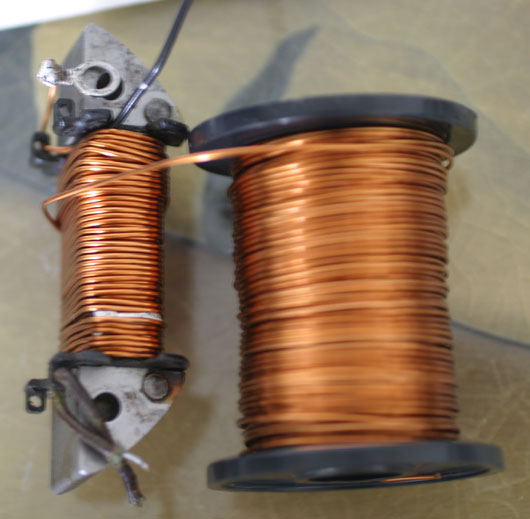 |
I'm now 80 turns in... No, it isn't the prettiest winding on the planet but as long as you work slowly and PULL the wire tight as you go, it will ensure the whole coil doesn't slip about with the engine vibrations... at 34 turns I added the (unused?) black wire 'take-off' and draped it along the windings so it appeared at the top - near the ground tag. Its now covered in one layer of windings (you can see the join between the windings near the bottom of the coil). |
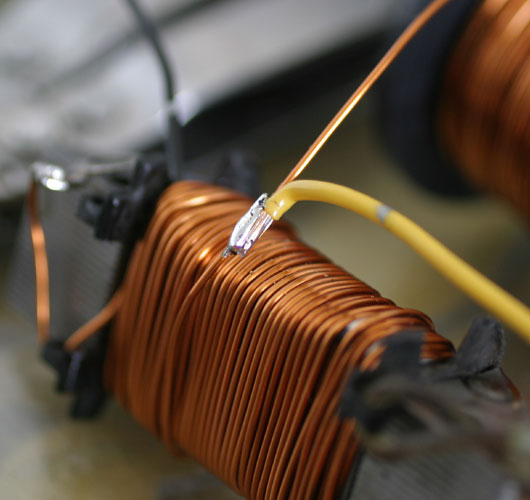 |
This is how the 'tapping' is made. This is the lighting 'take-off'. You need to scrape off the enamel/lacquer, and 'tin' the wire and cable... Once soldered, make sure it's a smooth joint, with no 'spiky bits' on the solder as they will poke through the insulation and potentially short out some of the turns .... |
 |
I made the joins to look like this. Each has 8-10 turns of PTFE tape to fully insulate the connection. The yellow wire is set at 90 degrees to the winding so that it will protrude nicely at the top of the finished winding. The next 40 turns will cover it nicely... |
 |
I've finished! 140 turns, two
cables protrude nicely from the windings (sadly, not visible in this
picture.) Black at the left of the winding and yellow to the right. The
end of the copper wire is cut, scraped and the last take-off is
soldered, ready to go through the "reminder hole".
On the last 2 turns, leave them a little loose so that the last bit of wire can go underneath... and when pulled tight, it sort of "knots" the last turn and stops it all from un-winding! |
| At this point, the windings' resistances were checked... Perfect! (see notes below) | |
| camera battery went flat. typical! |
I masked off the ends of the completed winding, so only the copper windings were visible then sprayed the winding with clear lacquer about 5 times with very wet, dripping coats... effectively 'glueing' the outer windings together. |
| sadly. no pic... | As a final touch, the windings (while still tacky) were tightly wrapped in cloth tape. This was also sprayed with 2-3 coats of clear lacquer to make the winding very firm and weather proof... |
|
YES! Lights are perfect and the battery isn't being boiled to death |
|
Notes
| Remember, "turns" does not equate to "length", as the coil is wound - the DIAMETER increases... Therefore, each layer of turns means LONGER wire per turn.... To be 100% correct - the LENGTH of wire between each take-off is the definitive measure. This is ignored in the Ohm measurements made here... | |
| Ground tag to Yellow wire (80
turns) Ground tag to Green/Yellow wire (140 turns) |
0.3 ohms 0.5 ohms |
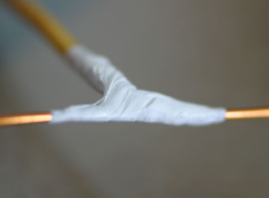
| The wire used for the take-offs I made are PVC coated and were further insulated again with PTFE tape up to where they emerge from the winding. To be strictly correct, the wire SHOULD be insulated with cloth or fiberglass tape - this is because the winding DOES get warm/hot in use and could melt the PVC... | |
|
DT250 1976 (model 512) |
|
| +---------+ Green/Red (charging take off) |----------+ Yellow (60 turns) (lighting take off) |----------+ Black (106 turns)| (unknown - n/c) +---------+ Ground Tag(140 turns) |
Total 140 turns 20 SWG Enamelled copper wire (0.9mm) |
| Back to the 512 page | Back to the Yamaha Page |
| Back to smiffy.com | |